We enjoy working with quality clients on quality projects because we are motivated to deliver our best work and always excited for more.
We are requirements-driven such that we can offer an accurate estimate of work and use them to drive your project towards success as defined by you.
25 years of start-up and business experience in the aerospace, electric-vehicle, petrol-chemical, service-industry, semiconductor and medical industries enables us to deliver on time and within budget.
Communicating to the manufacturer what is most important in terms of form, fit, and function, the limits of variance in repeatability, and the required precision is a time-consuming process. Engineering departments often struggle with developing standardized best practices for manufacturing drawings at each phase of the product development journey. Why? Well, it’s because only after a person has designed, manufactured, and functionally tested thousands of individual parts and assemblies can they truly engineer and produce excellent manufacturing drawings that offer low costs and short lead times.
Especially with the advent of 3D printing and 5th-axis CNC machining of complex designs, which are the most challenging to provide excellent drawings for, designers and engineers no longer have to master the discipline. They can simply submit their .stl file and have a part in their hands that is most likely not manufacturable by any other process. What’s worse, the learning process from design to documentation to manufacturing to testing and iteration is broken, resulting in incompetent engineers and designers costing their companies greatly, while relying on large development budgets or cheap offshore labor to manufacture their costly designs.
We are all about finding quick and easy solutions to problems. Leveraging the ISO 2768 tolerance standard for manufacturing drawings is a perfect fit. It not only saves engineering departments big bucks at the end of the year, considering the thousands of hours saved on engineering salaries, but also increases the department’s throughput while pleasing suppliers with quick and easy-to-understand manufacturing drawings.
In this article, we present a quick fix for rapid development or the prototyping phase and one of the most eloquent solutions to creating drawings for exteremely complex geometry. It doesn’t make sense to waste so much time and money on perfect production drawings down to every detail when a simple and clutter-free “Critical-To-Function” drawing, leveraging the ISO 2768 standard, can get the job done.
ISO 2768: An International Standard For Dimensional Tolerances
ISO 2768 is a set of international standards for tolerances in mechanical engineering. It is often used in the 3D printing and CNC machining industries for the production of complex parts because complex parts are so time consuming and difficult to dimensions and tolerance for designers and engineers. The standards cover three main categories: general tolerances, tolerances for linear and angular dimensions, and tolerances for form and position.
Critical-to- Function Drawings – Applying ISO 2768 to a Drawing
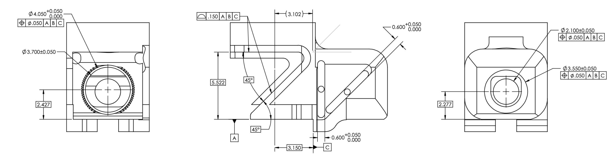
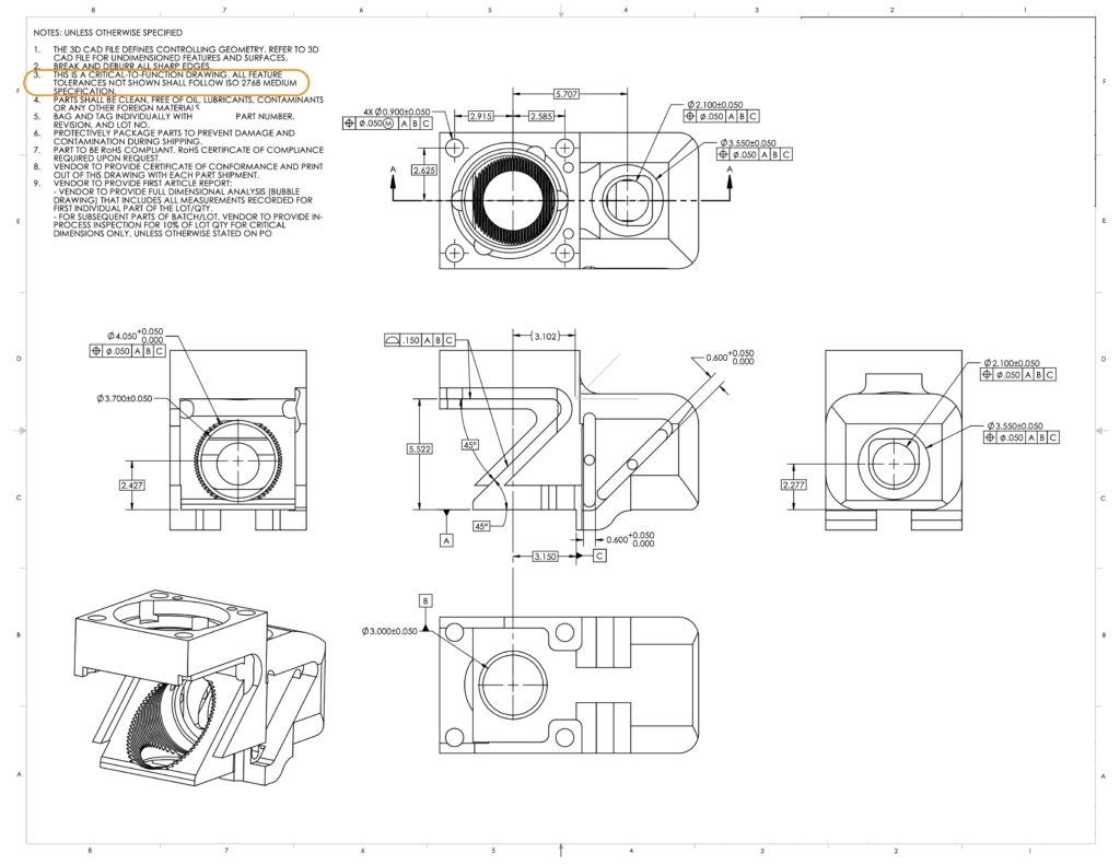
It’s quite simple really, add a note to the notes section of the drawying that reads: “THIS IS A CRITICAL-TO-FUNCTION DRAWING AND ISO 2768 APPLIES TO ALL DIMENSIONS AND FEATURES UNLESS OTHERWISE SPECIFIED.” Then, it’s as easy as adding dimensions/tolerances to the most critical of features on the drawings that are tighter than what is specified in the designation. The following example is a complex 5th-axis CNC machined part of a client of ours. The client’s first submission was a disaster of a drawing, with dimensions and tolerances impossible to measure, theoretical centers (big no-no), and the manufactuer would be offended with such a submission. We simply guided them to the ISO 2768 Standard, and whalluh, a simple drawing, easy to understand is provided that the manufactuer can easily inspect.
Testing form, fit, and function for complex parts against the “m” designation of this standard should be the first step. If it works, the job is done. If there are issues, then the engineer can work backwards to tighten up only the areas needed.
ISO 2768 Part 1: Linear Dimensions, Angular Dimensions and Tolerance Ranges
Table 1 shows the tolerance class designation for linear dimensions, per the ISO 2768 standard. Bbest practices that hit the sweetspot for most manufacturing processes, especially CNC machining is the “m”, medium designation. Don’t turn your supplier against you by specifying the fine tolerances. In any design, there should only be a few critical tolerances that you can specify specifically outside this standard.
Table 1: Linear dimensions | Permissible deviationas in mm
Basic size range in mm
f (fine)
m (medium)
c (coarse)
v (very coarse)
0.5 up to 3
±0.05
±0.1
±0.2
–
over 3 up to 6
±0.05
±0.1
±0.3
±0.5
over 6 up to 30
±0.1
±0.2
±0.5
±1.0
over 30 up to 120
±0.15
±0.3
±0.8
±1.5
over 120 up to 400
±0.2
±0.5
±1.2
±2.5
over 400 up to 1000
±0.3
±0.8
±2.0
±4.0
over 1000 up to 2000
±0.5
±1.2
±3.0
±6.0
over 2000 up to 4000
–
±2.0
±4.0
±8.0
Table 2: External Radii and Chamfers | Permissible deviationas in mm
Basic size range in mm
f (fine)
m (medium)
c (coarse)
v (very coarse)
0.5 up to 3
±0.2
±0.2
±0.4
±0.4
over 3 up to 6
±0.5
±0.5
±1.0
±1.0
over 6
±1.0
±1.0
±2.0
±2.0
Table 3: Angular Dimensions | Permissible deviations in degrees and minutes
Basic size range in mm (shorter side of the angle concerned)
f (fine)
m (medium)
c (coarse)
v (very coarse)
up to 10
±1º
±1º
±1º30′
±3º
over 10 up to 50
±0º30′
±0º30′
±1º
±2º
over 50 up to 120
±0º20′
±0º20′
±0º30′
±1º
over 120 up to 400
±0º10′
±0º10′
±0º15′
±0º30′
over 400
±0º5′
±0º5′
±0º10′
±0º20′
ISO 2768 Part 2: Geometrical Tolerances for Features
Part 2 defines the tolerance ranges H, K and L. These are different from the fitting and clearance tolerance grades that also use letters and numbers. Similar to ISO 2768 Part 1, there are nominal ranges and deviations, but the difference is how we define those deviations.
Table 4: Straightness and Flatness Tolerances | Permissible deviations in mm
Table 4 defines Flatness and Straightness tolerance classes. Straightness controls how much a surface varies within a specified line on that surface. Another use of straightness is for the axis of a part to control how much bend or twist is allowed.
Ranges of nominal lengths in mm
H
K
L
up to 10
0.02
0.05
0.1
over 10 up to 30
0.05
0.1
0.2
over 30 up to 100
0.1
0.2
0.4
over 100 up to 300
0.2
0.4
0.8
over 300 up to 1000
0.3
0.6
1.2
over 1000 up to 3000
0.4
0.8
1.6
As mentioned before, Perpendicularity has distance units (mm or in). Similar to Flatness, we define two planes separated by a gap equal to the permissible deviation in Table 5. We control the 90 degrees angle indirectly since we’re measuring whether the surface is in the permissible region or not.
Table 5: Perpendicularity Tolerances | Permissible deviations in mm
Ranges of nominal lengths in mm (shorter side)
H
K
L
up to 100
0.2
0.4
0.6
over 100 up to 300
0.3
0.6
1
over 300 up to 1000
0.4
0.8
1.5
over 1000 up to 3000
0.5
0.8
2
Table 6: Symmetry Tolerances | Permissible deviations in mm
Table 6 shows the tolerances for Symmetry and permissible deviations for two features on a part that are uniform across a datum plane.
Ranges of nominal lengths in mm
H
K
L
up to 100
0.5
0.6
0.6
over 100 up to 300
0.5
0.6
1
over 300 up to 1000
0.5
0.8
1.5
over 1000 up to 3000
0.5
1
2
Table 7: Run-out Tolerances | Permissible deviations in mm
Table 7 corresponds to Run-out, which is the total variation that a surface can have when the part is rotated around a datum’s axis. Notice that the marked surface is in tolerance even though it is not perfectly cylindrical.
Circular Run-out
H
K
L
–
0.1
0.2
0.5
You may have noticed that there is no table defined for parallelism. This is because ISO 2768 Part 2 defines parallelism as equal to the numerical value of the size tolerance or the flatness/straightness tolerance, whichever is greater.
Conclusion
ISO 2768 covers enough of the tolerance and geometric characteristics used in manufacturing to be used in the early development of a part or for complex parts that are incredibly difficult to documen.